Running system on sparcv8leon-gr740-mini 
These instructions describe how to run Phoenix-RTOS on the sparcv8leon-gr740-mini target. Note that the build
artifacts, including the system image should be provided in the _boot directory. If you have not built the system
image yet, please refer to the Building Phoenix-RTOS image section.
Connecting the board
Connect the board to the computer using a USB cable. The board provides a 4-channel FTDI Serial to USB converter, with the following assignments:
Channel 0 -
if00- used for GR740GRMONJTAG connection,Channel 1 -
if01- interfaces to CertusPro-NX FPGA JTAG,Channel 2 -
if02- used for console, interfaces to GR740UART0on the board,Channel 3 -
if03- interfaces to CertusPro-NX FPGA UART.
Flashing the Phoenix-RTOS system image
The process comes down to a few steps, described below.
Connecting to the board using GRMON
First, check on which JTAG channel the GRMON detects the board. To do this, run the following command:
grmon -ftdi -jtaglist
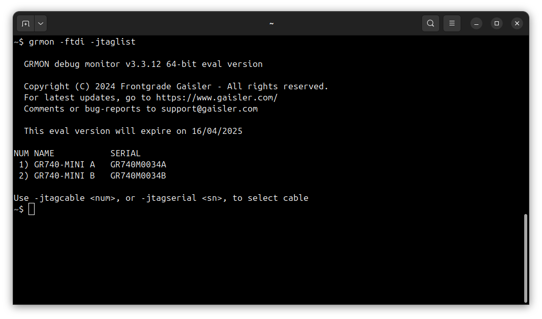
The JTAG connection to the GR740 processor is present on the GR740-MINI A connector. To connect to the board, run the following command:
grmon -ftdi -jtagcable 1 -sddcs
How to get GRMON
Download the GRMON software from the official website.
After downloading the archive, extract it and optionally add the
grmonbinary to thePATHvariable.
Uploading the system image
There are two ways of uploading the system image to the board:
Uploading the entire system image to the onboard flash memory,
Uploading only the necessary files to the onboard flash memory.
Method 1 is straightfoward because it requires uploading a single file at the flash start address 0xc0000000. However,
it is much slower than method 2, which skips the padded parts of the image.
Method 1: Uploading the entire system image
To load the system image to the onboard flash memory, run the following commands in the GRMON monitor:
flash load -erase phoenix-rtos-project/_boot/sparcv8leon-gr740-mini/flash0.disk 0xc0000000
You can then verify the uploaded image by running the following command:
verify phoenix-rtos-project/_boot/sparcv8leon-gr740-mini/flash0.disk 0xc0000000
Method 2: Uploading only the necessary files
Method 2 skips the padded parts of the image, which makes it faster than method 1. To upload only the necessary files
to the onboard flash memory, you need to upload the files to offsets on the flash specified by
phoenix-rtos-project/_targets/sparcv8leon/gr740/nvm.yaml file. The offsets are specified in the nvm.yaml file in the
phoenix-rtos-project/_targets/sparcv8leon/gr740 directory. The nvm.yaml file contains the following information:
flash0:
  size: 0x8000000 # 128 MB
  block_size: 0x20000
  padding_byte: 0xff
  partitions:
    - name: plo
      offs: 0x0
    - name: kernel
      offs: 0x20000
    - name: rootfs
      offs: 0x100000
      size: 0x500000
    - name: ptable
      offs: 0x7fe0000
      size: 0x20000
This means that plo.img should be uploaded at offset 0x0, part_kernel.img at offset 0x20000, rootfs.jffs2
at offset 0x100000, and part_ptable.img at offset 0x7fe0000.
To upload the files to the onboard flash memory, run the following commands in the GRMON monitor:
flash load -erase phoenix-rtos-project/_boot/sparcv8leon-gr740-mini/plo.img 0xc0000000
flash load -erase phoenix-rtos-project/_boot/sparcv8leon-gr740-mini/part_kernel.img 0xc0020000
flash load -erase phoenix-rtos-project/_boot/sparcv8leon-gr740-mini/rootfs.jffs2 0xc0100000
flash load -erase phoenix-rtos-project/_boot/sparcv8leon-gr740-mini/part_ptable.img 0xc7fe0000
You can then verify the uploaded images by running the following commands:
verify phoenix-rtos-project/_boot/sparcv8leon-gr740-mini/plo.img 0xc0000000
verify phoenix-rtos-project/_boot/sparcv8leon-gr740-mini/part_kernel.img 0xc0020000
verify phoenix-rtos-project/_boot/sparcv8leon-gr740-mini/rootfs.jffs2 0xc0100000
verify phoenix-rtos-project/_boot/sparcv8leon-gr740-mini/part_ptable.img 0xc7fe0000
Starting the execution
Before starting the system, you need to determine on which serial port the board is connected. To do this, run the following command:
ls -l /dev/serial/by-id
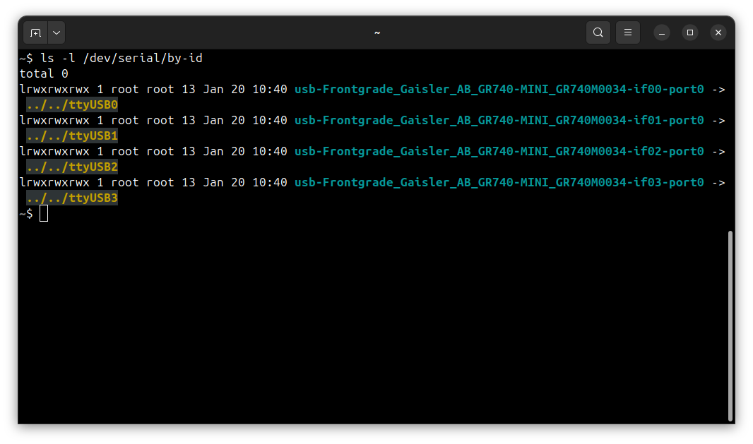
The serial console will be available on if02 channel, which in this case is connected to /dev/ttyUSB2. To connect
to the serial console, run the following command in a separate terminal:
picocom -b 115200 --imap lfcrlf /dev/ttyUSB2
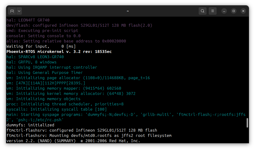
To start the execution you may reset the board by pressing the reset button or run the following commands in the
GRMON monitor:
ep 0xc0000000
run
Using Phoenix-RTOS
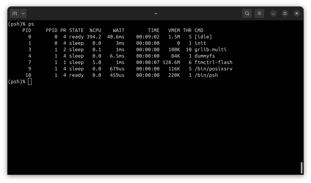
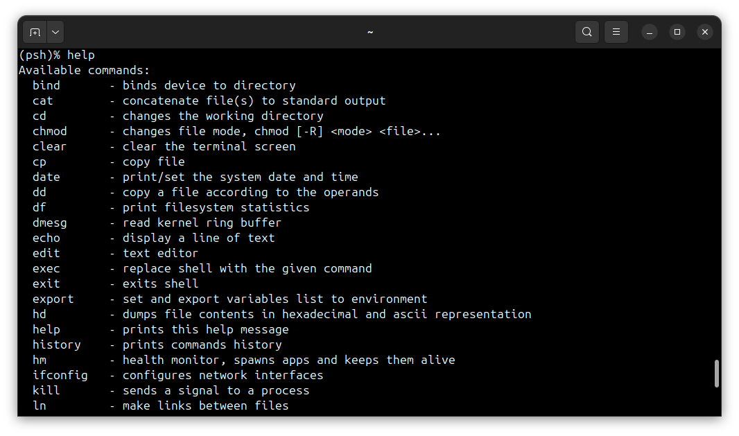
Phoenix-RTOS will be launched and the psh shell command prompt will appear in the terminal.
Note: You can also enter
ploby pressing any button within some time after reset.
To get the available command list type:
help
To get the list of working processes type:
ps